MIL-DTL-25708F
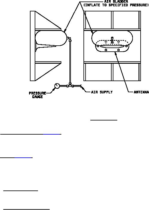
FIGURE 3. Static load test.
4.8 Resistance to solvents (see 3.4.5). Completely immerse the sample antenna in each test liquid [aviation
turbine fuel grade JP-5 (MIL-DTL-5624) and hydraulic fluid (MIL-DTL-5606) for 24 hours. Upon removal, shake or
wipe excess surface liquid from the antenna. Impedance test (see 4.5.2) shall be made and VSWR shall be as
specified in the applicable specification sheet (see 3.1).
4.9 VSWR (see 3.6.7). The VSWR of the antenna shall be measured as specified in 4.9.1, 4.9.2, or 4.9.3. The
antenna shall be mounted flush in the center of a 4-foot diameter circular ground plane. Precautions shall be taken to
insure that the reflected energy does not effect the VSWR measurements greater than 4 percent of the maximum
VSWR specified in the applicable specification sheet (see 3.1). The overall accuracy of VSWR measurements shall
be such that the (absolute VSWR) = (measured VSWR) ± 0.08 (maximum specified VSWR-1). VSWR
measurements shall be made before and after each environmental test specified in 4.5.7.
4.9.1 Slotted line method. VSWR measurements shall be made over the frequency range specified in the
applicable specification sheet (see 3.1) at increments not greater than 25 MHz. The measured data shall be
recorded.
4.9.2 Swept slotted line method. VSWR measurements shall be recorded by an X-Y recorder. The trace shall be
an X-Y plot of VSWR versus frequency plotted with a limit of 1 octave per plot at a minimum sweep rate of 30
seconds per frequency band. If the antenna under test exhibits an abrupt change in VSWR, the sweep rate shall be
further slowed to assure that the pin of the X-Y recorder can follow these changes. The trace shall be marked at
frequency increments of not greater than 25 MHz and labeled at not greater than four times the increment. The plot
shall display a nomograph that converts dB/cm to VSWR, and shall identify the antenna, the test data, the general
and detail procedure and the maximum allowable VSWR. Using the VSWR trace, the VSWR shall be tabulated at the
frequency increment. Prior to accomplishing the VSWR measurement, adjustments should be made to insure that
the frequency and sweep width of sweep signal generator are set to the desired bandwidth within the limitation of the
equipment. Precaution shall be taken to insure that the X-sensitivity of the recorder is adjusted to accommodate the
entire sweep and that the plot will be approximately in the center of the graph paper for the entire frequency range.
15
For Parts Inquires submit RFQ to Parts Hangar, Inc.
© Copyright 2015 Integrated Publishing, Inc.
A Service Disabled Veteran Owned Small Business