MIL-DTL-25707F
4.5.5 Radiation pattern (see 3.6.5). Measurements of the radiation pattern shall be made with the antenna mounted in the
center of a four-foot diameter circular ground plane, in its normal mounting configuration, assuming the ground plane represents the
aircraft skin. In order to mount a curved antenna on a ground plane (which is flat), an intermediate fixture may be used which
mounts to the flat ground plane on its one side and simulates curved aircraft skin (matching the antenna curvature) on its opposite
side. The radiation patterns shall be made on a continuously recording radio range of the automatic type. Care shall be taken to
avoid errors due to reflections from nearby objects, including earth. Azimuth (Φ) patterns shall be made at zenith (Θ) angles of 70,
80, 90, 95, 100, 105, and 110 degrees, at the zenith angle of maximum radiation, and at any other zenith angle deemed advisable
(see figure 1). Vertical patterns shall be made in the plane through the centers of the antenna and of the probe and in the plane at
right angles thereto. Like patterns shall be made for comparison, using the same test power levels on a matched quarter-wave
stub antenna except that a single vertical pattern will suffice. Unless otherwise precluded by procuring activity contract, the design
of the quarter-wave stub antenna and matching section shall be approved by the acquiring activity prior to manufacture. The above
tests shall be made at frequencies of 960, 1050, and 1220 MHz but need not be repeated after environmental exposure.
4.5.6 Polarization test (see 3.6.6). Polarization tests shall be conducted in the continuously recording radio range in the same
manner as the tests for radiation pattern, in accordance with one of the standard methods discussed in Chapter 11 of IEEE Std
149-1979. Polarization tests need to be made at only one frequency (1,050 MHz). For each test antenna, the axial ratio of the
polarization ellipse shall be determined in each of the following directions (θ, Φ) degrees: (90, 0), (90, 90), (90, 180), (90, 270),
(60, 0), (60, 90), (60, 180), (60, 270), (30, 0), (30, 90), (30, 180), (30, 270). The measurements shall then be repeated on a quarter-
wave stub antenna mounted at the same location, at identical power levels and sensitivities.
4.5.7 Environmental tests (see 3.5). Environmental tests shall be in accordance with MIL-STD-810 in the sequence shown
herein. Following each of the first six environmental tests below, the antenna shall meet the electrical requirements of 3.6.2
through 3.6.6.
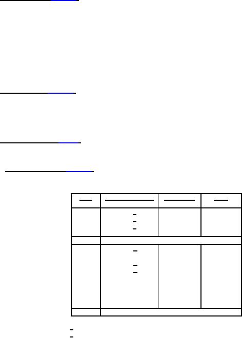
4.5.7.1 Temperature altitude (see 3.5.2). Method 520 of MIL-STD-810 shall be tailored for variations in temperature and altitude
only. This test shall not include vibration or humidity environments.
a.
Test conditions:
Temperature (oC)
Altitude (ft)
Time
Step
1
-62 1/
site
2 hours
-54 1/
site
2
---
-54 1/
75,000
3
---
-10
site
---
4
5
Standard ambient conditions
6
125 2/
site
16 hours
7
95
site
4 hours
125 2/
8
site
30 minutes
150 2/
9
site
10 minutes
60
10
50,000
4 hours
90
11
50,000
30 minutes
-10
12
75,000
4 hours
20
13
75,000
30 minutes
45
14
75,000
10 minutes
15
Standard ambient conditions
1/ For MIL-DTL-25707/2 antennas use -48.3 °C.
2/ For MIL-DTL-25707/2 antennas use +96.6 °C.
Step 1.
With antenna de-energized, adjust chamber to step 1 conditions. After antenna temperature is stabilized,
maintain conditions for 2 hours.
Step 2.
With antenna de-energized, adjust chamber to step 2 conditions, and maintain. After antenna temperature is
stabilized, operate antenna at lowest specified input voltage. The antenna shall operate satisfactorily
immediately following the specified warm-up time. All characteristics likely to be affected by low temperature
shall be checked first. If time to check exceeds 15 minutes beyond the warm-up time, the test item shall
again be stabilized at the step 2 temperature and the operational check continued.
Step 3.
With antenna de-energized, adjust chamber to step 3 temperature and stabilize antenna temperature.
Energize the antenna at highest specified input voltage and adjust chamber pressure to step 3 altitude. At
step 3 pressure and temperature, the antenna shall be checked for satisfactory operation.
7
For Parts Inquires submit RFQ to Parts Hangar, Inc.
© Copyright 2015 Integrated Publishing, Inc.
A Service Disabled Veteran Owned Small Business