MIL-DTL-22641F
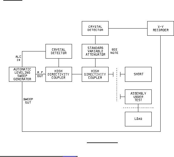
4.6.2.1 Procedure. VSWR of the assemblies shall be measured using a system as shown on figure 1, or
equivalent, and shall be no greater than the value specified. Tuners and pads shall be used, where necessary, to
reduce residual VSWR of the system to a level which will assure accurate results before connecting the assembly
under test.
FIGURE 1. VSWR test setup
4.6.3 RF insertion loss (when specified) (see 3.5). The adapter shall be tested as shown in figure 2. Included in
the insertion loss of the adapter is the reflection and dissipating loss of two standard test adapters - one for each
interface of the adapter under test. Before performing the measurement on the adapter under test, the following two-
step checkout procedure shall be performed:
Step 1 - The insertion loss of [1] and [2] of figure 2 shall be measured.
Step 2 - The insertion loss of [4] and [3] shall be measured.
To perform the measurement on the adapter under test, [1], [5], and [3] shall be inserted as shown, and the insertion
loss shall be measured.
NOTE: Use 20 dB pad when calibrating for coaxial end measurements, then remove.
7
For Parts Inquires submit RFQ to Parts Hangar, Inc.
© Copyright 2015 Integrated Publishing, Inc.
A Service Disabled Veteran Owned Small Business