MIL-DTL-3928/15G
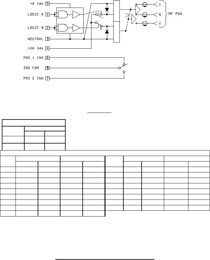
POSITION 1. ENERGIZE TERMINAL 1. N CONNECT TO 1,
2 IS OPEN CIRCUIT
POSITION 2. ENERGIZE TERMINAL 2. N CONNECT TO 2,
1 IS OPEN CIRCUIT
SCHEMATIC
Logic truth table
Logic signal
RF
path
A
B
N-1
1
0
N-2
0
1
Dimensions
Inches
Millimeters
Inches
Millimeters
Letter
Letter
Max
Min
Max
Min
Max
Min
Max
Min
A
1.15
1.09
29.2
27.7
K
.450
.430
11.43
10.92
B
.28
.22
7.1
5.6
L
.890
.870
22.61
22.10
C
.19
.13
4.8
3.3
M
1.37
1.31
34.8
33.3
D
.20
.14
5.1
3.6
N
.35
---
8.9
---
E
.12
.06
3.0
1.5
P
1.80
---
45.7
---
F
.130 dia
.110 dia
3.30 dia
2.79 dia
Q
.34
.28
8.6
7.1
G
.230
.210
5.84
5.33
R
.28
.22
7.1
5.6
H
.450
.430
11.43
10.92
S
.53
.47
13.5
11.9
J
.680
.660
17.27
16.76
NOTES:
1. Dimensions are in inches.
2. Metric equivalents are given for general information only (1.00 inch = 25.4 mm).
3. Unless otherwise specified, tolerances are ± .010 (± 0.25 mm) for three place decimals and
± .03 (± 0.8 mm) for two place decimals.
4. Round corners of case may be squared.
FIGURE 11. Switch configuration and schematic, PIN M3928/15-16 - Continued.
23
For Parts Inquires submit RFQ to Parts Hangar, Inc.
© Copyright 2015 Integrated Publishing, Inc.
A Service Disabled Veteran Owned Small Business